Surface Mount vs Through-Hole Assembly: How to Choose
The short answer: default to SMT, pull specific components to through-hole
If you are weighing SMT vs through hole for a new board, start with a default and adjust from there. Surface mount suits most of the parts on most boards. It packs more onto less copper, it runs on automated lines, and it keeps the cost per board down as quantities grow.
Through-hole earns its place one component at a time. A connector that gets plugged and unplugged all day, a terminal block that takes a heavy cable, a large power part that carries real current: each of these can justify a drilled hole and a leaded joint on a board that is otherwise all surface mount. The board as a whole can use both methods.
That gives you a simple way to work. Begin with every part as SMT. Then ask which parts face mechanical load, high current or heavy heat, and move only those to through-hole. The rest of this post covers the factors that flip a part from one column to the other, and what the result means for how your board gets built.
What each technology actually does
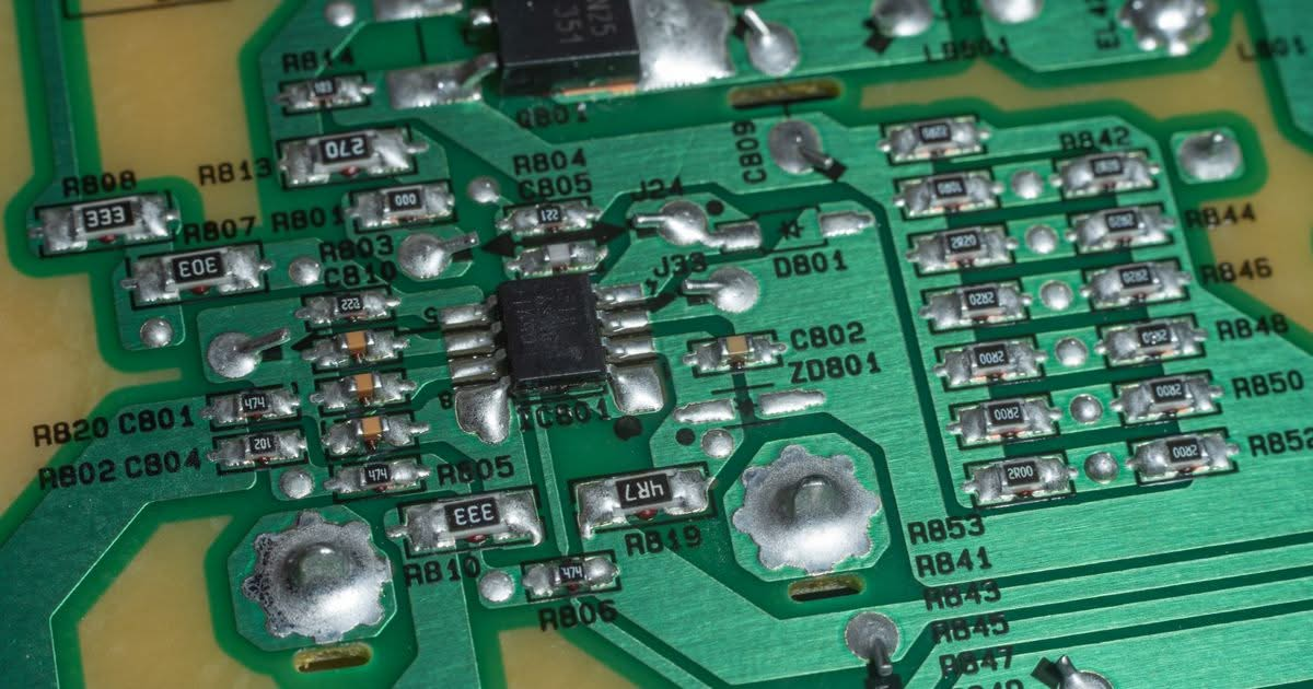
Surface mount places components directly on pads on the board's surface. Solder paste goes onto the pads, a pick-and-place machine sets each part on its paste, and the board travels through a reflow oven that melts the paste into finished joints. Because the parts sit on the surface, they can be very small, and both sides of the board can carry them.
Through-hole components have leads that pass through drilled, plated holes in the board. The leads are soldered on the far side, by wave soldering for many joints at once, by selective soldering for specific spots, or by hand. Because the lead runs through the board, the part is held by the barrel of the hole as well as by the solder around it.
Most engineers asking about the two already know this much. What matters is how the differences play out on your particular bill of materials, and that is where the next sections spend their time.
Where SMT wins
A fair look at smt assembly vs through hole starts with size. The smallest package in common production use, 01005, measures 0.4 mm by 0.2 mm. Parts that small have no leads to push through a hole, and they let a designer fit a full circuit into an enclosure that would never hold a through-hole version of the same design.
Fine-pitch devices follow the same logic. QFPs and micro-BGAs at 0.4mm pitch are routine for surface mount and impractical for any other method. If your design leans on a dense processor, a memory package or a compact RF section, SMT is the only practical route for those parts.
Speed is the other advantage. Placement machines work from programmed data and need no hands on each part. On our MY12 pick-and-place system, high-speed mounting runs up to 21,000 components per hour, with 144 feeders loaded for the job. A separate fine-pitch mode, at 1,500 components per hour, slows the machine down for QFPs and micro-BGAs at 0.4mm pitch. Every surface-mounted board then passes automatic optical inspection, which scans for missing, incorrect or misplaced components before the board moves on.
Paste application has its own tooling. Our MyData MY500 jet printer deposits solder paste in dots as small as 5 to 12 nanolitres, on pitches down to 0.5mm, so the paste step does not depend on a physical stencil.
SMT pays off most on high-mix boards with many different part values, on compact products where every square millimetre counts, and on runs where the machine's speed multiplies across hundreds or thousands of boards. Our surface-mount and through-hole circuit board assembly services run from quick-turn prototypes to volume production in one facility.
Where through-hole still wins
In a through hole vs smt comparison, mechanical load settles most of the arguments. A connector takes force every time a cable is plugged in or pulled out. A surface-mount pad holds a part by a thin layer of copper bonded to the laminate, and repeated stress can lift it. A through-hole lead sits in a plated barrel that anchors the part on both sides of the board, so the joint resists that pull far better.
The standards back this up. For Class 2 and Class 3 assemblies, J-STD-001 calls for a minimum of 75% vertical solder fill in a plated through-hole. The joint is built and inspected to that measure, and that is why a through-hole joint under a connector earns trust for physical load. Our technicians and inspectors work to the IPC-A-610 and J-STD-001 workmanship standards we apply to every soldered assembly.
Vibration and heat point the same direction. Boards that live on equipment that shakes, or that carry heavy current through large transformers, power connectors and big electrolytic capacitors, benefit from the mass and mounting strength a leaded part offers. Those components are also physically large, so the space saving of a surface-mount package offers little to them.
Through-hole has a practical edge in the shop too. A leaded part can be removed and replaced by hand with ordinary tools, which makes it friendly to prototypes, to boards that need field repair and to designs still changing. A fine-pitch BGA rework is a specialist job. A through-hole resistor swap takes a technician a few minutes.
Our through-hole assembly technicians bring more than 40 combined years of experience, and each one is trained in-house. That depth matters when a board has hand-soldered joints that must meet the same acceptance criteria as the machine-placed ones.
Why most boards end up mixed, and what that means for your build
A board built with only one technology is the exception. Connectors, terminal blocks, relays and heavy passives often stay through-hole even on a design that is mostly surface mount, because the decision runs by component. Following the rule from the start of this post, a typical board lands on SMT for most of its parts and through-hole for a handful of the ones that carry load.
Mixed technology pcb assembly changes the build sequence. The surface-mount side goes first: paste, placement, reflow and optical inspection. Then the through-hole parts are inserted and soldered, by wave, selective or hand methods, depending on the board and the part. Each added step brings more handling and more setup, so the way you assign parts to each technology shapes how many passes the board needs.
This is where the facility behind the build matters. Splitting a mixed board between two vendors adds a shipment and a handoff, and each handoff adds time. We run both processes under one roof in Lockeport, NS, so a mixed board moves from reflow to through-hole soldering without leaving the building. Our mixed-technology assembly is set up for exactly that, and combining the two processes in one facility reduces cost and lead time for customers who need both on a single product.
For you as the designer, the practical takeaway is to treat the through-hole parts as a deliberate choice. Group them where you can, keep them on one side of the board where the layout allows, and label which ones are there for mechanical reasons. A short list of through-hole parts with the reason for each gives a manufacturing team what it needs to plan the sequence well.
How volume and prototyping change the decision
The surface mount vs through hole decision looks different at five boards than at five thousand. At high volume, automated placement spreads its setup across many boards, and SMT wins on cost per unit. At prototype quantities, setup is a larger share of the total, and the choice of method has to account for it.
Through-hole is forgiving at low quantities. A technician can solder a handful of boards by hand with no programming. That makes leaded parts a sensible choice for early revisions where the design is still moving and a part might change between builds.
Surface mount has traditionally carried a setup cost at low quantities because paste printing calls for a stencil. Our MY500 removes that step. It programs paste deposits straight from Gerber data or a scanned board image, so there is no stencil to order for a prototype run. Changes can be made pad by pad, with no reflow cycle needed to verify them. A prototype can then use the same SMT process as production, and you learn how the real design behaves early.
The sensible approach for most projects is to settle the through-hole parts first, since they depend on mechanical needs, and let the quantity decide how much of the rest is worth optimizing.
Getting the mounting decision right before assembly starts
Component-by-component mounting choices get made and checked at the quoting stage, when changes cost the least. That is why the first step in how we work is Review & DFM: your files are reviewed for manufacturability before assembly begins, so pad layout, part availability and mounting choices are looked at together.
If you have a design in progress, send us your Gerber or CAD data and a current bill of materials with manufacturer part numbers. We will review the files and come back with a clear, considered quote. Our team is ready to talk through which parts belong on which side of the surface mount and through-hole line, and you can Request a Quote to start the conversation.