Wire Harness vs Cable Assembly: What the Difference Means for Your Build
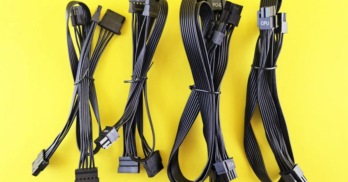
Wire harness vs cable assembly is a question that shows up on a lot of drawings and RFQs, and the answer changes how a part is built, documented and tested. The two terms get used loosely, so a clear read of the difference saves a round of emails with your supplier. This post defines both, then follows the difference down to the bench, where terminations, crimps and test results are decided.
Cable Assembly or Wire Harness? The Physical Difference
The difference between cable assembly and wire harness comes down to shape and path. A cable assembly is one or more conductors enclosed in a single continuous outer jacket, with a terminated end on each side. It runs from point A to point B and carries one type of signal, or a small group of related signals. A coax run from a bulkhead connector to a circuit board is a cable assembly. So is a shielded multi-conductor cable with a plug on each end.
A wire harness is a group of individually routed wires and cables bound together along a defined path. At set points the bundle splits, so one main trunk reaches several destinations. It starts at a trunk and fans out to multiple connectors, and the finished shape follows the space inside the product it serves.
Set the two side by side and the contrast shows up in three places. The first is the jacket. A cable assembly gets its outer jacket from the raw cable, while a harness gathers its wires under tape, sleeving or conduit applied during assembly. The second is the ends. A cable assembly has connectors at one or both ends, and a harness has a connector or terminal at every branch. The third is geometry. A cable assembly is a line, and a harness is a tree.
Many real builds mix the two. A harness can include a jacketed cable as one of its legs, and in that case the harness drawing governs the whole part.
Cable assembly manufacturers and harness manufacturers use different tooling for a reason. A single jacketed cable suits automated cut and strip equipment, and a branching build suits a formboard and skilled hands. Because buyers and shops use the two terms loosely, a drawing titled "cable" can describe a harness, and the quote comes back priced for the wrong process. Naming the right one on the RFQ gets the right process quoted from the start.
What the Difference Means for Routing and Protection
A cable assembly carries its protection with it. The jacket is built into the raw cable, so moisture, abrasion and chemical exposure are handled by the material you choose before assembly begins. Shielding, where the signal needs it, sits under that jacket as part of the same cable.
A wire harness has no shared jacket. Each wire carries only its own insulation, so the protection is engineered into the build during assembly, and the choices follow from where the harness will run. A braided sleeve guards against abrasion where the bundle rubs a bracket. Corrugated conduit handles longer runs through a chassis. Tape wrap holds a bundle tight in a small envelope. Heat-shrink at branch points seals the spot where the trunk splits, which is where wires are most exposed and most likely to be pulled.
Vibration, fluid and temperature swings drive those decisions. A harness inside a dry instrument enclosure may need little more than tape and ties. A harness on a vessel or in an outdoor cabinet faces moisture, salt and thermal cycling, and its covering has to be specified for that exposure. The drawing should say which covering goes on which segment, because the shop builds what the print describes.
Routing belongs to the same conversation. A cable assembly is flexible and takes its path from the installer. A harness is built to a fixed layout with branch lengths set in advance, so it drops into the product the same way every time.
What It Means for Terminations, Crimping, and Continuity Testing
This is where the choice of term shows up on the bench. A cable assembly is typically terminated with automated cut, strip and crimp tooling set up for a defined connector pairing at each end. The same two terminations repeat on every unit, which suits a machine. Coax work follows the same logic, with stripping and termination steps matched to the cable and connector.
Wire harness assembly involves more hand work. Each branch can call for a different wire gauge, color or terminal type, and terminals are placed by hand at the branch points. A technician follows the wire schedule wire by wire, so the skill on the bench and the quality of the documents both carry weight.
Whichever one is being built, the crimped connection has to meet a minimum pull-force before it is accepted. A crimp that looks tidy can still hold poorly, so it is tested by load. A widely used military and aerospace crimping reference sets minimum crimp tensile strength by conductor size: 57 N (13 lb) for 22 AWG, 92 N (21 lb) for 20 AWG, 183 N (41 lb) for 16 AWG and 459 N (103 lb) for 12 AWG. The figures climb with wire size because a larger conductor must resist a larger pull. A harness with several gauges on one print has several pull-force requirements on the same part.
Continuity testing comes next. It verifies that every wire reaches its correct pin and that no wire reaches a pin it should not. On a cable assembly that check covers a short list of connections. On a harness the list is longer, and every branch is verified end to end.
Both builds are accepted against the same class of standard. IPC/WHMA-A-620 is the industry-consensus standard for requirements and acceptance of cable and wire harness assemblies, and Allendale builds and inspects its cable and wire harness work to the IPC/WHMA-A-620 requirements and acceptance criteria described on the quality page. One standard for both means a crimp, a strain relief or a solder cup is judged by the same criteria whichever term sits on the drawing.
Why Harness Documentation Runs Heavier
A cable assembly needs a drawing with a wire or cable schedule and connector callouts. That package describes one path, two ends and the cable between them, and it fits on a sheet.
A wire harness needs a full drawing package. The wire schedule lists every wire with its gauge, color, start pin and end pin. A schematic shows how the circuits connect. A formboard or routing drawing shows every branch length, the position of each branch point and the covering on each segment. Each of these documents answers questions the technician would otherwise have to guess at.
Incomplete harness documentation is where rework starts. A missing branch length means two builds come out different, and an unspecified sleeve means each technician picks a different one. A wire color left off the schedule becomes a question for the engineer in the middle of a production run.
The extra detail up front is the thing that keeps a repeat build identical to the first one. The first harness proves the drawing, and every later harness is built from the same pages. Teams that put that effort into the package find their second and tenth orders go through the bench as smoothly as the first.
Which One Does Your Product Need?
A quick rule settles most cases. One signal type, one connector at each end and no branching describes a cable assembly. A one-off custom cable assembly for a single sensor run is a good example: one cable, two terminated ends, one job.
Wires that need to reach three or more destinations from a shared trunk, inside a defined physical envelope, in a harsh operating environment, describe a wire harness. A full instrument panel is the classic case, with power, signal and ground wires all leaving the same bundle for different connectors.
Some products need both, with a harness inside the enclosure and cable assemblies running out to remote sensors or antennas. Sending the whole set to one shop with a clear parts list keeps the drawings consistent from one build to the next. If you are unsure which term applies, send the drawing or a sketch of the connections, and the answer follows from how many destinations the wires reach.
Built and Tested Under One Roof
Allendale's sub-assembly technicians build and test coax cables, wire harnesses, transformers, inductors and other sub-assemblies, in any quantity from a single prototype to volume production. The cable and sub-assembly capability at our Lockeport, Nova Scotia facility includes a CoaxStrip5300, an EcoStrip 9300 single-strip wire cutter and an HS 4140 cable label printer. Cable and wire harness work is inspected against IPC/WHMA-A-620.
Because both builds happen in the same shop, to the same standard, the term on your print does not decide where the work goes. A cable assembly and a harness for the same product are built, inspected and shipped by one team, so the fit between them is settled in one place.
Send us your files and requirements, and we will review them and return a clear, considered quote. Request a Quote and tell us what the build needs to do.